

NEURAL NARRATIVES
The software environment for the Neural Narratives project consists of several applications for simulation, video tracking, visual rendering, video mapping, sound synthesis, and audio spatialization. These application run in parallel and exchange information and control data with each other via the open sound control protocol (OSC).
1 Simulation
The simulation software which has been custom developed in C++ is responsible for modelling the actuated virtual body extensions. The simulation functionality is divided into several parts: body architecture, mass-spring simulation, propul- sion simulation, collision detection and resolution, numerical integration, neural network simulation, sensing and actuation.
1.1 Body Architecture
The body architecture part of the simulation manages the topology of the virtual body extensions. Each extension con- sists of one or several so-called body segments that are organized into tree like structures. Both the computational repre- sentations of the dancers’ physical bodies that are derived from video tracking and the virtual body extensions are struc- tured in such a way. The simulation takes care of translating the various body segments into corresponding mass-spring systems and of preserving their connectivity and directional constraints (Fig. 4, left).
1.2 Mass Spring Simulation
The mass-spring simulation (Fig. 4, middle) models spring tensions forces according to Hooke’s law. In addition, it also simulates a directional restitution force that pushes springs towards a preferred rest direction which is relative to the di- rection of the preceding spring. Finally, all the mass points experience a damping force that is proportional and opposite to their velocity. The body architecture is represented within the mass-spring simulation as linear or branching sequen- ces of springs. Successive springs within a sequence share their respective mass points (Fig. 4, left).
1.3 Propulsion Simulation
The propulsion simulation implements a physically rather contrived way of calculating forces that cause body segments to propagate through space. These forces are derived from the mass points’ relative velocity with respect to the direc- tion of their corresponding springs (Fig. 4, right). The propulsion force points in a direction opposite to the spring and its length is proportional to the dot product between the velocity difference between mass point 1 and 2 and a vector that is perpendicular to the spring’s direction. Furthermore, a damping force is calculated that opposes the movement of a body segment and thereby imitated the viscosity of a surrounding medium. The damping force is the sum of two vectors.
The first vector points into the direction of the spring. The second vector points is a direction that is perpendicular to the spring. The length of both vectors is proportional to the dot product between the velocity of mass point 1 and the vector perpendicular to the spring.
1.4 Neural Network Simulation
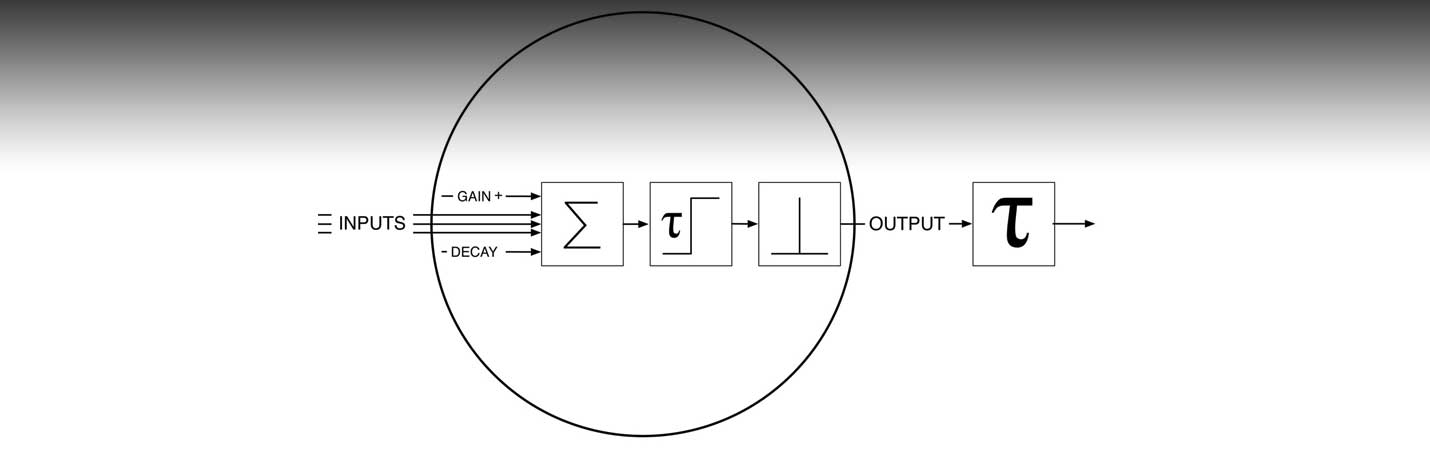
The simulation software allows the construction of time-delayed recurrent neural networks. The characteristics of these networks is as follows. Signals and activity levels are represented as continuous values whereas time is discrete. Signals propagate with a time delay and attenuation factor in between interconnected nodes. Signals that arrive concurrently at a node are passed through a transfer function that adds the node’s gain and decay values to the sum of the incoming signals. The output of this function determines the node’s activity level. This value is then passed through a step function that serves as threshold in order to determine if the node should produce an activity spike. If the node’s activity level ex- ceeds this threshold, the node fires, its activity is reduced by a preset amount, and the node enters a refractory period du- ring which it cannot fire again (Fig. 5).

Figure 4. Body Architecture, Mass-Spring and Propulsion Simulation. Left: Schematic depiction of a corporeal structure consisting of multiple branching body segments and its corresponding mass-spring representation. The mass-spring system is depicted as black lines (springs) and black circles (mass points). The body segments are depicted as black outlines. Middle: Depiction of mass-spring forces. Forces are shown as grey outlined arrows (DaF: damping force, SF: spring force, DiF: directional force). The currently evaluated spring and its mass points are depicted in solid black. The preceding spring is depicted in solid grey. The current spring’s rest direction and length is depicted as dashed black line. Right: Depiction of propulsion forces. Forces (PF: propulsion force, DF1: damping force vector 1, DF2: damping force vec- tor 2) are shown as grey arrows. mass point velocities (V1: mass point 1 velocity, V2: mass point 2 velocity) are shown as black outlined arrows. The spring normal direction (N) is depicted as black filled arrow.

Figure 5. Neural Network Simulation. The graphical symbols in the schematic depiction of a neural node are (from left to right): Summation of input signals, gain and decay, refractory period limit and activity threshold, output signal spike, signal propagation time delay.
1.5 Sensing and Actuation
The activity of the neural network can affect the properties of the mass-spring system and vice versa. This functionality is realized via the implementation of sensing and actuating elements. Each of these element is associated with a spring and a neural node. A sensing element maps a property of its spring into an activity value of its neural node (Fig. 6, left). An actuating element maps the activity of its neural node into a property of its spring (Fig. 6, middle). At the moment, the fo- llowing sensing and actuation elements exist: Length sensors map the deviation of a spring’s length from its rest length into a neural activity. Directional sensors do the same for the deviation of a spring’s direction from its rest direction. Len- gth motors map neural activity into a new rest length for a spring. Directional motors map neural activity into a new rest direction for a spring. An example body extension with its neural network, sensors and actuators is shown in Fig. 6, right.

Figure 6. Left: schematic depiction of sensors. A directional sensor (DS) maps a spring’s directional deviation into an ac- tivity level of a neuron (N). A length sensor (DS) maps a spring’s length deviation in a neuronal activity level. Middle: sche- matic depiction of motors. A directional motor (DM) maps a neuronal activity into a spring’s rest direction. A length motor (LM) maps a neuronal activity into a spring’s rest length. Right: manually designed neural network and directional actua- tor system for a multi-arm body extension.
1.6 Collision Detection and Resolution
The simulation provides means to define bounding volumes to which individual body segments can be assigned. The- se volumes are constructed from 2D contours that are extruded into the Z-direction. A volume consists both of a hard limit surface and a soft limit region. In addition, a volume can act as an outer boundary, preventing body segments from leaving a particular region, or it can act as inner boundary, preventing body segments from entering a particular region. Bounding volumes can either be hand designed or automatically derived from the video tracked contours of one or seve- ral dancers (Fig. 7). The collision detection and resolution mechanism applies to mass points that try to traverse a hard limit surface. If such a collision is detected, the corresponding mass points are instantaneously repositioned onto the li- mit surface. If the mass points enter a soft limit region, a force is applied to gradually push to them back. This force is proportional to the depth of the mass point’s penetration into the soft limit region.